Example 24: Depth-Resolved Multilens Matrix Point PSF
Example 23 fitted a single rigid cap to the
diverging multilens element of Haidour et al. (Nat. Commun. 2025, s41467-025-64911-z).
The paper builds a large 3-D imaging probe by tiling 252 of these elements on an
18×14 grid at 5.48 mm pitch, driven at 1 MHz, and characterises its
point-spread function versus depth (their Fig. 2 / Supplementary Fig. 2). The
acquisition is a synthetic-aperture sequence: the 16 elements of the central 4×4
block each fire one diverging wave in turn, and every element of the whole probe
receives with uniform unit apodization (a fixed full aperture, not a focused F-number).
The 16 single-element echoes are compounded coherently on receive to synthesise a focus
everywhere. This example reproduces it with
CustomTransducer (252 copies of the example-23
free-aspheric cap), fires the 16-source sequence at three point targets, delay-and-sums the
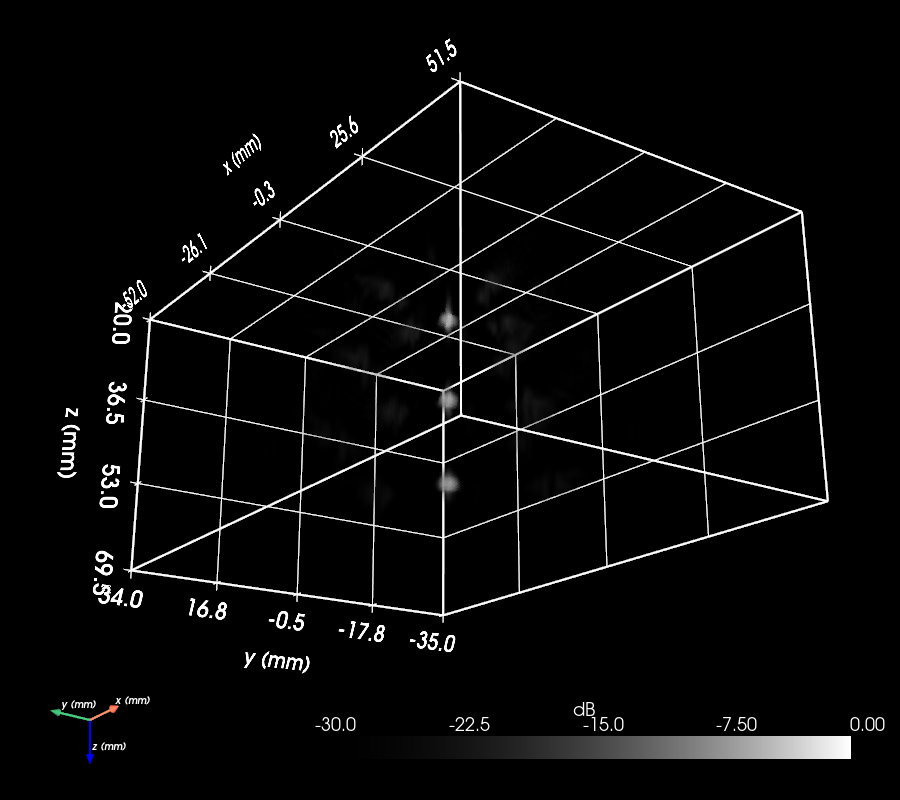
compounded echoes into a 3-D volume, and renders it the way the paper does — grayscale, in
dB, with a linear opacity transfer function over a −30 dB display window.
Assembling the matrix
The diverging cap is reused straight from example 23 (same fit), so a change to the lens
there flows through here. 252 curved caps × 16 transmits is heavy — keep NO_SUB
modest, and preview the geometry with sim.show() before the simulation.
from example23_optimize_radial_element import optimized_aspheric
from esdiva.transducers import CustomTransducer

element = optimized_aspheric(no_sub_diameter=20)  # one diverging cap
# 18×14 centres on a 5.48 mm grid → positions_mm (252, 3)
tx = CustomTransducer([element] * 252, positions_mm, frequency_Hz=1e6)
rx = CustomTransducer([element] * 252, positions_mm, frequency_Hz=1e6)
TX and RX are separate copies of the same geometry. Both apertures get a 2-cycle 1 MHz impulse response (bare drive) so the pulse-echo spectrum is band-limited.
The 16-source diverging sequence
Each of the 16 central elements (the middle 4×4 block) fires one diverging wave, driven by
a one-hot apodization so only that element emits while every element receives. The
16 events run through sequence_rf and are then
compounded by das_volume. Receive uses a fixed full
aperture (rect weighting, every element at every depth) — the paper's uniform unit
apodization — so the broad element directivity, not a focused F-number, sets the effective
aperture.
Where does a lens element sit for the beamformer?
The decisive detail is the element's acoustic datum. A rigid diverging cap has its apex
at z = 0 and its rim recessed to z < 0, but it radiates a spherical wave whose centre of
curvature — the virtual acoustic source — lies behind the aperture.
RadialProfileTransducer.virtual_source_m
returns that point by a least-squares circle fit of the element's own surface (here
≈ −1.8 mm). Referencing the delay-and-sum to the aperture plane (z = 0) instead
mis-times every echo by the lens's own curvature and defocuses the compounded transmits.
The example references both the transmit virtual source and the receive element position
to that depth, and removes the constant 2|z_vs|/c round-trip pedestal it introduces with
t_offset_s (so the targets still beamform to their true depth). A sweep over the three
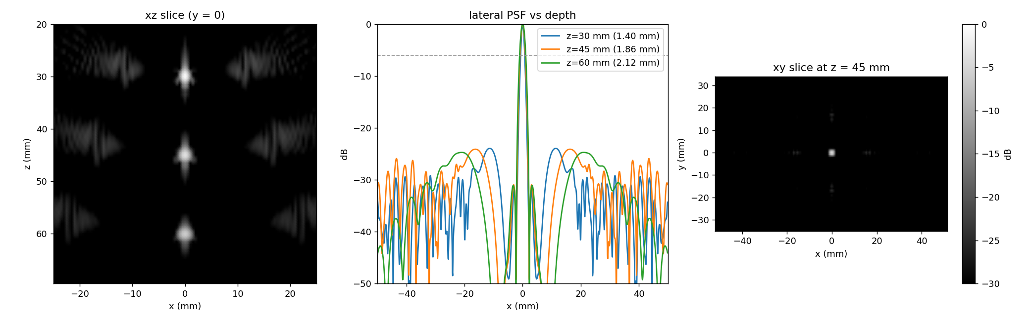
candidate datums — aperture plane, rim, virtual source — shows the lateral −6 dB width
collapse as the datum moves to the virtual source:
| depth | z = 0 |
rim | virtual source |
|---|---|---|---|
| 30 mm | 3.25 mm | 2.52 mm | 1.40 mm |
| 45 mm | 2.84 mm | 2.38 mm | 1.86 mm |
| 60 mm | 2.51 mm | 2.31 mm | 2.12 mm |
The monotone ordering (aperture plane worst, virtual source best) is the discriminating evidence that the lens curvature — not the array aperture — set the earlier ~2.5 mm lobe.
The Fig. 2-style volume render
The beamformed volume is envelope-detected along depth, log-compressed to dB, and
volume-rendered with PyVista using a grayscale colormap, a linear opacity transfer
function over a −30 dB display window (opacity ramps linearly from transparent at
−30 dB to opaque at 0 dB), and the "smart" volume mapper (ray-cast). A dark theme
(black background, all text white — ruler,
colorbar, box, axes) with the z axis pointing down (camera.up = (0, 0, −1), the
ultrasound depth convention) puts the probe at the top and the three targets below. The
render box is the paper's 104 × 70 mm lateral phantom, framed over the 20–70 mm depth
range on a 0.5 mm grid — the main lobe is ~1 mm, so 1 mm voxels render it ~1 voxel wide
(blocky), while 0.5 mm puts 2–3 samples across it so the spots render smooth; the main lobes
are measured separately on fine 0.1 mm planes through each target. The volume is rendered
twice — once with the 252-cap probe mesh overlaid above the box (tx.get_mesh(), coloured
by per-element apodization and self-lit with ambient=1) and once with the volume alone.
Three panels give the quantitative view: the xz slice through the three targets, the lateral PSF profiles at each depth with the −6 dB resolution marked, and the xy grating-lobe star.
How close is this to the paper?
With the virtual-source datum the lateral −6 dB resolution is 1.40 mm at 30 mm, widening to 2.12 mm at 60 mm as the fixed array subtends a smaller angle with depth — the shallow value is close to the paper's quoted 1.06 mm. The peak grating lobe sits at about −24 dB (paper −22.4 dB), and the eight-arm grating geometry matches. The axial resolution is ~1.3 mm, pulse-limited by the 2-cycle burst. The residual gap to 1.06 mm lives in the single-rigid-cap approximation of the real two-material lens and in the paper's unpublished Beamforming processing, so this example reproduces the measurable array physics and the depth trend without claiming to match the raw main-lobe width exactly.
Grating lobes are expected here
The 5.48 mm pitch is 3.56 λ, far above the λ/2 that suppresses grating lobes, and a diverging element does not taper them the way a large flat element would. The regular off-axis replicas in the PSF (the star at ±11–13 mm in the xy slice) are those grating lobes — a real property of this coarse, large-pitch matrix, not a simulation artefact. A finer pitch or stronger element directivity would push them down.